Total Pageviews

Thursday, December 29, 2011

Prezi Presentation on the UT Tyler NASA Orion Project


Friday, September 30, 2011

Pull Test Complete!

The video below is a pull test on a strut end, as performed by Jim Mills on our Tinius Olsen tensile testing machine.  When Jim pans the camera over to the control panel on the machine, you will see the force hovering at about 11,000 pounds (more than 5 tons) -- and the maximum force applied was 12,600 lbs.  Starting at about 48 seconds, watch for the dramatic deformation.

So . . . which will fail first:  the ball joint part of the strut?  The threaded rod?  The weld?


The specimen was loaded at 0.02 in/min, and using the smallest cross-sectional area of the part (which would be based on the minor diameter of the thread pitch) the strut end withstood 71 ksi of tensile stress. 

Check back later for some pictures!

Wednesday, September 28, 2011

Adjustable Struts In Use!


This is a video of the pallet bring raised back to the nominal location after moving it to a post stroked condition during testing yesterday afternoon at NASA Johnson.  Christie Sauers commented as folllows: "Pretty amazing how easily it moves!  Notice we aren’t even using the cheater bars.  It actually moves so easily that we will be adding some locking nuts very soon to keep them from moving when you hold on to the struts for stabilization/leverage."  Thanks for the video, Christie!


Tuesday, September 27, 2011

MISSION ACCOMPLISHED!

The pallet has been installed in the mockup!  Congrats to everybody involved in this project!


Thursday, August 4, 2011

Strut Changes

Below are some pictures dealing with an issue discovered at delivery:  the pallet struts do not the full 8" range of motion.  Jim Mills is working on fixing the problem, and the images below are being provided to NASA engineers to evaluate any issues that could arise as a result of fixing the problem.  One of the challenges in engineering design is determining the effect that one seemingly minor design change may have on the rest of the design.  In this instance, there is concern about interference of cut-off bolt heads and nuts with the adjustment threads inside the struts.

Here are Jim's comments on the images:  The threaded 5/8” bolt in the center simulates the screw size only, disregard the bolt head of that element. The bolts used are ¾” to simulate the drop bolt head size of 1  1/8” across the flats. The last two are ¾” nuts to simulate the best case scenario of trimming the drops, via the 1” hole in the side, to mostly just hex without much screw remaining.


Pallet and Strut Delivery!

Below, you can see the pallet and struts waiting between RBN and RBS to be loaded up for the trip to Houston.

Ready to go!

The pallet outside the mockup at NASA Johnson.
Jim Mills and Mike Singleton delivered the pallet and struts to NASA.  While there, they enjoyed some awesome scenery and cool NASA sights.
Mike at Rocket Park.
Jim and the medium fidelity Orion capsule mockup.

Thursday, July 28, 2011

Final Coat of Paint

Pallet Center Section

Pallet Side Sections

Struts


Strut Close-up

Tuesday, July 26, 2011

And Now for some Color!

Jim Mills has been busy today painting the pallet, struts, and hardware.  Here are the pictures!  The paint used for the project is manufactured by Preservo.

Hardware (brackets).

Struts.

Pallet sections.


Pallet and Struts "Primed" and Ready!

The pallet and struts have been primed and are ready for painting!  A big thanks to Mr Mills for taking care of this task, and providing the pictures.  As soon as the parts are painted, they are off to NASA for installation in the Orion capsule.

The pallet sections.

The struts, with pallet sections visible at the bottom.

Brackets and hardware.

Another view of the pallet and struts.


Monday, June 20, 2011

Weld Testing with Dye Penetrant

One of the NASA requirements for the pallet is to perform dye penetration tests on the welds to check for surface defects at the welds.  The kit used was a Crack Check Visible Red Dye Pentrant Inspection System made by  Dynaflux.  The surface of the weld is thoroughly cleaned, the dye is applied, allowed to penetrate (capillary action will draw it into cracks and crevices that are not visible to the naked eye), the dye is removed from the surface.  Once the dye is removed from the surface, any cracks or surface defects will then be visible.  The images below show the testing being performed, and the results.


Initial application of the dye
Dye removed from surface, showing a very good weld.
Results of testing, again showing a very solid weld.
End of one of the adjustable struts.
Close-up of results for one of the adjustable struts.  The area around the weld shows no dye present.
Again, excellent results for one of the adjustable struts.  No dye present at the weld!
This type of testing is known as non-destructive testing because you do not have to damage the part in order to perform the test.  Our goal is to perform DESTRUCTIVE testing on one of the struts -- pulling it apart in the tensile testing machine -- and on a duplicate of the pallet.

Tuesday, June 14, 2011

FABRICATION COMPLETE!

The pallet and strut fabrication is now complete . . . the pallet weighs in at 482 lbs and the struts combined weigh 210 lbs.  After painting and final hardware, the total weight will be around 700 lbs.

The three pallet sections.

Another view of the pallet pieces.
Completed strut ends.

Wednesday, June 8, 2011

Pallet Structure is COMPLETE!

The pallet and strut bracket mounting is complete, and all welds have been smoothed out on the pallet.  This is the most important milestone in the completion of the project.  The pallet and struts for the Orion capsule medium fidelity mockup will be ready to deliver to NASA before too long!  However, some minor details remain, such as performing dye-penetration testing on the welds, sand-blasting the pallet, and painting the pallet and struts.

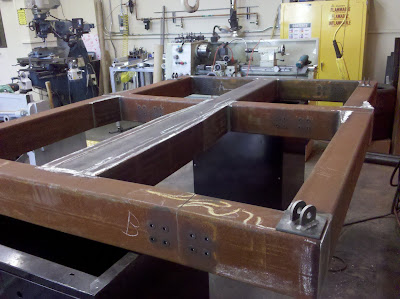
The pallet with vertical strut connection brackets welded to the pallet.
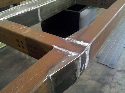
This figure shows a detail of welds that have been ground flush with the surface.  It is important to remember that when a weld is done properly, it is as strong as (or sometimes stronger) than the base materials that are being welded together.

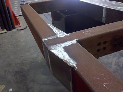
Detail of welds after smoothing.
Below is another full-length view of the pallet.  Recall that it will be sandblasted (to clean off all debris) and painted before delivery at NASA Johnson.

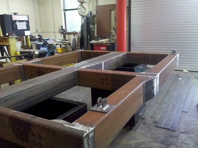
Another full view of the pallet.


This figure focuses on the center portion of the pallet, where changes in width were required to insure that the overall pallet dimensions were the same as the Lockheed Martin flight design.


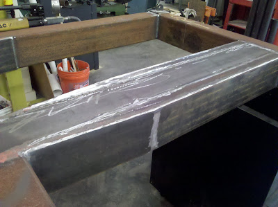
Close-up view of the center of the pallet.


Close-up of another weld.
And finally . . . Jim Mills used 3 lbs worth of grinding disks to smooth out the welds!  The figure below shows what is left of them!
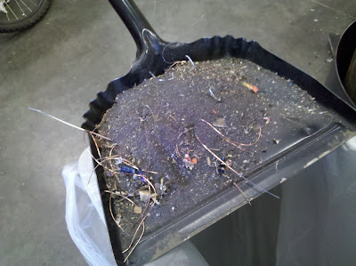
What's left of 3 lbs of grinding disks and smoothed welds!

Tuesday, June 7, 2011

Pallet almost Complete!

The progress on manufacturing the pallet continues!

Basic pallet structure complete.

Close-up of center of pallet.
The pictures that follow are details of the welds required.


Note the weld in the center, at the T-section.

This section is quite interesting:  note the plate welded at an angle (see far left of picture).

Another close-up of a weld for a T-section -- Mr. mills welding glove can be see to the far right.

Here were see a plate welded at an angle.  This was necessary to ensure that the pallet has the same exterior dimensions as the Lockheed Martin pallet in the actual flight-version of the Orion capsule.

 Observe the welding clamp in the upper right-hand side of the image.

Note this weld:  not being a welder myself, I figure it must be quite challenging to arrange the workpieces to achieve the correct shape and remain within dimensional tolerances.

This image is particularly important:  here you can see where two sections of the pallet are bolted together.  This required that the bolt holes be drilled at precise locations to coincide with matching bolt holes on an inside support piece used to connect the two sections together.

Here you can see where additional steel plate was welded into place to ensure the pallet dimensions match those of the actual flight model.


This is a computer generated solid model of the pallet -- before it was ever built.  It is fascinating to look at the actual product side-by-side with the solid model built in Solid Edge.

Another view of the pallet.