Total Pageviews

Saturday, April 23, 2011

Updated FEA Analysis

The figure below shows how the pallet is being modeled in Algor to determine the stresses and displacement.  This model combines an 8,000 lb loading (includes NASA's safety factor of 4) and the weight of the pallet itself.  The struts are modeled as truss elements, carrying a load only along their length, and are colored purple.  The Blue and orange arrows represent forces acting on the pallet.
  
FEA model of the pallet.
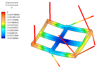
Two cases have been investigated:  one using 1/4" steel channel as the primary structural material, and the other using 3/8" steel channel.
Displacement for the 1/4" thick steel channel model.

Von Mises stress for the 1/4" thick steel channel model.
Additional analysis is being performed to improve the model so that it better represents actual loading conditions and gets accurate results.

Dimensioned Pallet Drawing

Below are the dimensioned drawings for the final pallet design.  The primary pallet structure will be made of either 3/8" or 1/4" steel tubing.  After consulting with the machine shop manager here at UT Tyler -- Mr. James Mills -- the team did some additional analysis to determine if the 1/4" channel would be sufficiently strong for the design -- this would be ideal because it would result in a weight reduction of over 200 lbs. 
 
Dimensioned drawings of the pallet.

Thursday, April 7, 2011

Pallet to Strut Brackets

The team has made a great deal of progress since the last update!
First, here is the preliminary design of the pallet to strut bracket
3D Conceptual Model
Dimensioned Drawings of Brackets 

The team has also finished preliminary design of the sleeves that will be used to attach the three sections of the pallet together.  The sleeve design and bolting patterns are shown below. The bolt patter is overdesigned for moment and shear capacity, and the bolt holes can be drilled and tapped.  Note that buckling effects should be analyzed due to reduction in metal at the bolt holes.   The sleeve itself is built up using A36 steel plate, and the inside of the inner sleeve can be built up to 1/2" thick as needed to handle buckling.
Bolt Pattern at Sleeve Connections

Critical Cross Section


Wednesday, April 6, 2011

New Design Update!

After consultation with NASA (aka, Jeff Fox, Christie Sauers and Leland Dysart), the team has designed to go with steel as the material of choice.  By switching to steel, the manufacturing time can be reduced.  First, there are structural shapes already available, such as the square tubing shown below, that can meet the required pallet dimensions better than the aluminum C channel originally selected.  Steel will also be easier to weld than aluminum.  The pallet will be stronger -- however, it will be heavier!

Typical square tubing, OnlineMetalsStore.com
Before switching to square tubing, finite element analysis was performed using Autodesk Algor Simulation 2011 to compare the stress and displacement experienced when using C channel versus square tubing, both  made of A36 steel.  Keep in mind that the loads applied are actually four times greater than expected in order to assure that the design will be strong enough.  Below are some of the slides the team presented to NASA at the last design review.  Based on these results, the square tubing is the preferred design cross section.

The tube displaces on 0.039 inches, compared to 1.8 inches for the C-channel.  The cross section of the tubing makes it considerably stiffer.

The square tube experiences about 42 ksi maximum von Mises stress while the channel experiences 138 ksi.


The design has also been revised to ensure access to lockers that will be beneath the pallet in the mockup.  The latest pallet design (called Version 3) is shown below.  The material used in the tube channels is typically ASTM A500 Grade B, a low carbon steel that includes copper as one of its alloying elements.  Its ultimate strength is 56 ksi -- which is above the 42 ksi estimated by the current FEA analysis. 

Pallet viewed from the top (3D model created in SolidEdge)
Pallet viewed from the bottom (3D model created in SolidEdge).  The webbing you see adds additional stiffness to that portion of the pallet.