Total Pageviews

Monday, June 20, 2011

Weld Testing with Dye Penetrant

One of the NASA requirements for the pallet is to perform dye penetration tests on the welds to check for surface defects at the welds.  The kit used was a Crack Check Visible Red Dye Pentrant Inspection System made by  Dynaflux.  The surface of the weld is thoroughly cleaned, the dye is applied, allowed to penetrate (capillary action will draw it into cracks and crevices that are not visible to the naked eye), the dye is removed from the surface.  Once the dye is removed from the surface, any cracks or surface defects will then be visible.  The images below show the testing being performed, and the results.


Initial application of the dye
Dye removed from surface, showing a very good weld.
Results of testing, again showing a very solid weld.
End of one of the adjustable struts.
Close-up of results for one of the adjustable struts.  The area around the weld shows no dye present.
Again, excellent results for one of the adjustable struts.  No dye present at the weld!
This type of testing is known as non-destructive testing because you do not have to damage the part in order to perform the test.  Our goal is to perform DESTRUCTIVE testing on one of the struts -- pulling it apart in the tensile testing machine -- and on a duplicate of the pallet.

Tuesday, June 14, 2011

FABRICATION COMPLETE!

The pallet and strut fabrication is now complete . . . the pallet weighs in at 482 lbs and the struts combined weigh 210 lbs.  After painting and final hardware, the total weight will be around 700 lbs.

The three pallet sections.

Another view of the pallet pieces.
Completed strut ends.

Wednesday, June 8, 2011

Pallet Structure is COMPLETE!

The pallet and strut bracket mounting is complete, and all welds have been smoothed out on the pallet.  This is the most important milestone in the completion of the project.  The pallet and struts for the Orion capsule medium fidelity mockup will be ready to deliver to NASA before too long!  However, some minor details remain, such as performing dye-penetration testing on the welds, sand-blasting the pallet, and painting the pallet and struts.
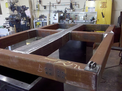
The pallet with vertical strut connection brackets welded to the pallet.
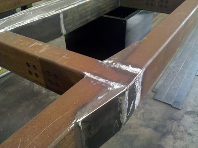
This figure shows a detail of welds that have been ground flush with the surface.  It is important to remember that when a weld is done properly, it is as strong as (or sometimes stronger) than the base materials that are being welded together.
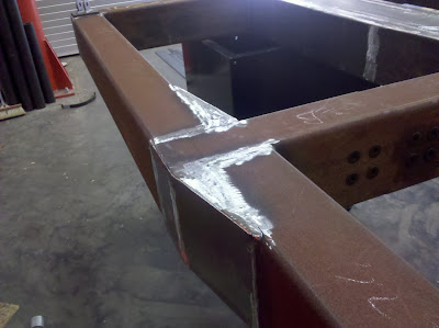
Detail of welds after smoothing.
Below is another full-length view of the pallet.  Recall that it will be sandblasted (to clean off all debris) and painted before delivery at NASA Johnson.
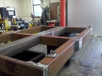
Another full view of the pallet.


This figure focuses on the center portion of the pallet, where changes in width were required to insure that the overall pallet dimensions were the same as the Lockheed Martin flight design.
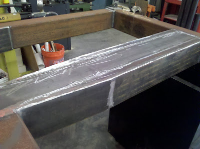

Close-up view of the center of the pallet.


Close-up of another weld.
And finally . . . Jim Mills used 3 lbs worth of grinding disks to smooth out the welds!  The figure below shows what is left of them!
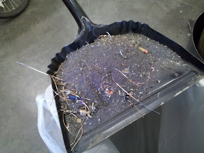
What's left of 3 lbs of grinding disks and smoothed welds!

Tuesday, June 7, 2011

Pallet almost Complete!

The progress on manufacturing the pallet continues!

Basic pallet structure complete.

Close-up of center of pallet.
The pictures that follow are details of the welds required.


Note the weld in the center, at the T-section.

This section is quite interesting:  note the plate welded at an angle (see far left of picture).

Another close-up of a weld for a T-section -- Mr. mills welding glove can be see to the far right.

Here were see a plate welded at an angle.  This was necessary to ensure that the pallet has the same exterior dimensions as the Lockheed Martin pallet in the actual flight-version of the Orion capsule.

 Observe the welding clamp in the upper right-hand side of the image.

Note this weld:  not being a welder myself, I figure it must be quite challenging to arrange the workpieces to achieve the correct shape and remain within dimensional tolerances.

This image is particularly important:  here you can see where two sections of the pallet are bolted together.  This required that the bolt holes be drilled at precise locations to coincide with matching bolt holes on an inside support piece used to connect the two sections together.

Here you can see where additional steel plate was welded into place to ensure the pallet dimensions match those of the actual flight model.


This is a computer generated solid model of the pallet -- before it was ever built.  It is fascinating to look at the actual product side-by-side with the solid model built in Solid Edge.

Another view of the pallet.

Friday, June 3, 2011

Strut Ends

Cut-away view of early strut design.
The struts are used to suspend the pallet from the forward bulkhead of the Orion capsule.  To the left is one of the very early (aluminum!) conceptual models for the adjustable struts.  Pay special attention to the cutaway section showing the interior of the strut.

The figure below shows the schematic of one of the short vertical struts in its final design form.  Note how the ball joint rod end is welded into place after the threads have been drilled out an a lead screw has been inserted.  This is then welded to the round plate at the end of the strut.  Welded to the plate is a guide bushing to support the lead screw.  A hex nut is then welded to the guide bushing.  This design allows the length of the struts to be adjusted as needed.  The manufactured parts for these strut ends, made by Jim Mills, are shown directly below the schematic.


Dimensioned schematic of a vertical strut with manufacturing instructions included.
Ball joint, threaded rod, end plate, guide bushing, and lead screw hex nut used to form each end of the struts.

Positioning of the end plate on the welding workstation to allow the guide bushing and hex nut to be welded into place.

Close-up of the strut end, after welding has been completed.

Strut ends, arranged on the welding workstation.
The figure below shows the strut ends on two completed struts, laying on the pallet.  The next figure shows two completed struts, with the ball joint ends screwed completely in.  It is interesting to take note of their size in relation to the pallet.  The struts for different positions on the pallet are of different length, so not all struts will be this long.

Ends of two completed struts.

Two completed struts and some of the completed brackets.

Manufacturing the Pallet/Strut Connection Brackets

The schematic for the pallet/strut connection brackets is shown below.  Each bracket is manufactured from three separate metal workpieces:  two square pieces that are machined to form the rounded "ears" and a rectangular base, all cut out of A36 1/4" steel plate.  All three workpieces are welded together to form the final bracket.


Schematic of the pallet/strut connector brackets, drawn by the team.
The picture below shows how Jim Mills is machining three of the bracket "ears" at the same time in the milling machine.  The cutting tool moves in a half-circle to remove the necessary material.  Some of the already completed "ears" can be seen at the bottom of the picture.  The image that follows shows three workpieces welded together to form a single bracket.  Some additional machining and grinding is required before the part is ready for installation.

Machining the pallet/strut connection brackets.
Welded pallet/strut connection brackets.
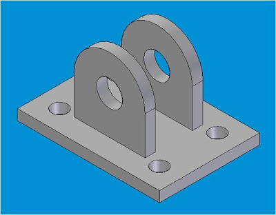
Finally, compare the brackets above to one of the solid model conceptual design images created by the team in Solid Edge.  All that is left is to drill the holes in the base.

Conceptual model of the pallet/strut connection brackets created in Solid Edge.

Thursday, June 2, 2011

Detail work on the Pallet


Prefab strut corner placed in CNC mill to do the inside chamfers required.

Close-up of the corner with inside chamfers clearly shown.
The pictures above show some of the detail work being done on one of the pallet sections (which has already been welded).  Note the tool (and its shape) used to cut the chamfers for the holes.  According to James Mills, who is responsible for manufacturing the pallet and struts, this was a bit challenging to setup with available equipment.  This part of the work is being done on a Smithy CNC (computer numeric controlled) milling machine. 

The picture below shows one of the pallet sections setup in one of the other milling machines (Atrump vertical milling machine, shown to the left) we have in the Fabrication Laboratory.  Thanks to Jim Mills for providing these pictures!

More detail work on the pallet!
The image below shows why these holes are necessary:  to connect the pallet sections together.  The pallet is divided into three sections that will be assembled INSIDE the Orion capsule mockup on location at NASA.  This is needed for two reasons:  first, the assembled pallet will not fit through the entry hatch; second, the assembled pallet will weight about 600 lbs!  By dividing it into three sections it can fit through the entry hatch and will be easier to position inside the mockup. 

Red ellipses show in the sketch above show the break points for the three pallet sections.


Holes drilled into two of the pallet sections, coinciding with the lower portion of the figure above. Note the chamfers!